Battery development is stuck in build-test-iterate. Most engineering domains moved to simulation-first workflows decades ago, but battery teams still build cells, run charge-discharge protocols on a bench for weeks, and redesign based on what they learn. Charging strategy, one of the most consequential design decisions for any battery product, gets validated the same way: slowly, expensively, and with almost no visibility into what's actually happening inside the cell.
Batteries earn this treatment, to some extent. The geometry is simple but the physics and parameters are difficult, context-dependent, and shift over the cell's lifetime. A charging profile that works well at 25°C and 10% state of charge may accelerate degradation at 5°C and 60% state of charge. BMS simulation gives engineering teams a way to explore those interactions before committing to hardware, and to compare candidate strategies under identical assumptions rather than sequential bench experiments.
This guide covers how battery engineering and BMS teams use simulation for charging strategy validation, what the workflow looks like in practice, and where the boundaries between R&D insight and production deployment still exist.
Why battery teams simulate charging strategy before hardware
A single charge-discharge aging test takes weeks. Comparing five candidate charging profiles across three temperature conditions and two state-of-charge windows means months of bench time and dozens of cells. If the results reveal a problem with taper logic or thermal derating, you start over.
Simulation compresses that cycle. Teams can run hundreds of charging scenarios in hours, compare tradeoffs quantitatively, and narrow the design space before any physical cell is committed. You still need bench testing, but you arrive at the bench with far better questions.
The U.S. Department of Energy's fast charging gap assessment explicitly notes that development of new charging protocols that may extend battery life should be considered. Protocol design remains an active engineering challenge.
Charging strategy is a battery physics problem as well as a controls problem
BMS charging logic is often treated as controls engineering: set current limits, define voltage thresholds, implement temperature derating tables. That framing undersells the problem.
Charging behavior depends on electrode kinetics, solid-state diffusion, thermal gradients, and degradation mechanisms that shift over the cell's lifetime. A controls engineer can implement a taper rule. Knowing where to set the taper threshold requires understanding how the cell's internal states respond to different current profiles, and that knowledge comes from electrochemical models, not lookup tables.
The core tradeoff: fast charge versus long life
Every charging strategy navigates the same tension. Customers want fast charging. Cells want gentle treatment. The charging strategy's job is to find the best compromise between charge time, heat generation, lithium plating risk, and cumulative aging.
Higher currents generate more heat. Heat accelerates calendar and cycle aging. At low temperatures or high states of charge, aggressive charging can push the anode potential below the threshold where lithium plating begins. Plating is hard to reverse. Eventually it creates safety risks.
Research on the limits of fast charging under thermal and electrical considerations confirms that charging current should be controlled based on those limits. It is not a fixed value. The best strategy is rarely the fastest one. It's the one that meets charge-time targets while staying inside thermal and degradation boundaries across realistic operating conditions.
What BMS charging strategy validation covers
Charging strategy validation in simulation typically spans several layers of control logic: maximum current limits at each state of charge, voltage-based taper thresholds, temperature derating curves that reduce current when the cell is too cold or too hot, and state-of-charge windows that define when charging should taper or terminate.
Pack-level considerations add complexity. Cell-to-cell variation means the weakest cell in the string often dictates the pack's charging envelope. Balancing logic, managing voltage differences between cells during or after charging, is another element teams may represent in simulation.
What engineers optimize during charging profile simulation
Optimization targets for a charging strategy are rarely single-objective. Teams typically care about time to a target state of charge (often 80%), peak and average temperature during the charge event, projected degradation impact under repeated use, and robustness across ambient conditions.
A strategy that charges to 80% in 18 minutes at 25°C but causes significant plating at 5°C is not shippable. Simulation lets you test robustness alongside headline performance.
Why default charging profiles are rarely enough
Standard CC-CV charging is the default for most lithium-ion cells. It's simple, well-understood, and safe within conservative limits. It's also rarely optimal for a specific chemistry, pack design, and use case.
Research on multistage constant current strategies shows that staged profiles have shortened charging time and improved lifetime compared with CC-CV in multiple studies. A single constant-current phase doesn't adapt to the cell's changing internal resistance, temperature, and electrochemical state as it charges. And one-size-fits-all CC-CV breaks across chemistries because different cathode and anode materials have different voltage curves, thermal sensitivities, and susceptibility to degradation mechanisms like plating or SEI growth.
Charging strategies teams compare in BMS simulation
Teams typically evaluate several categories. Standard CC-CV serves as the baseline. Multistage constant-current profiles use two or more current steps, often starting higher and stepping down as SOC increases. Temperature-aware derating strategies reduce current based on measured or estimated cell temperature. SOC-dependent taper rules adjust current continuously rather than switching at a single threshold.
More advanced approaches use optimization or model-based adaptive charging, where the profile is computed based on modeled internal states rather than predefined. Optimization of multistage constant current fast charging has shown that tuned protocols can outperform default CC-CV on charging time, degradation, and temperature rise simultaneously.
Simulation makes these comparisons clean. You run all candidates against the same cell model, thermal assumptions, and operating conditions, eliminating the confounding variables that plague sequential bench experiments. Tools like the Ionworks Battery Protocol Simulator are built around this kind of controlled comparison workflow.
Rules-based versus model-based charging control
This distinction shapes both what simulation needs to capture and what's feasible to deploy.
Rules-based approaches use fixed thresholds and lookup tables. Taper current when voltage reaches 4.2 V. Reduce charging rate by 50% when temperature exceeds 45°C. Cut off charging below 0°C. These rules are straightforward to implement in BMS firmware and have decades of field reliability behind them. The limitation is conservatism. They don't adapt to the cell's actual internal state, so they leave performance on the table.
Model-based approaches estimate internal variables you can't directly measure: anode potential, lithium concentration gradients, local temperature at the electrode interface. Research on model-based fast charging of lithium-ion batteries demonstrates that anode-potential control can achieve approximately 15-minute charging while mitigating lithium plating, by constraining current so the anode potential never drops below 0 V versus lithium. Other work has used advanced single-particle models to analyze degradation effects during fast charging.
The gap between these in practice is significant. Model-based charging produces better strategies in simulation and in controlled lab settings. Deployment is harder. Production BMS hardware needs embedded state estimators, validated model parameters, and computational resources that many current platforms don't support. Simulation is where teams explore what's possible. Deployment waits for the hardware and embedded controls to catch up.
Comparing rules-based and model-based charging approaches
Dimension
Rules-based
Model-based
Primary inputs
Voltage, surface temperature, current, SOC lookup tables
Electrochemical model estimates (anode potential, concentration gradients, internal temperature)
Strengths
Simple to implement, field-proven, low computational cost, predictable behavior
Adapts to actual cell state, extracts more performance from the same hardware, reduces unnecessary conservatism
Limitations
Cannot respond to internal states, conservative across all conditions, leaves charge-speed headroom unused
Requires validated cell model parameters, higher computational load, sensitive to estimation errors
Deployment readiness
Production-ready on virtually all BMS platforms today
Primarily R&D and advanced development; production deployment requires embedded state estimators and real-time compute budgets most BMS hardware doesn't yet support
In practice, most teams ship rules-based control and use model-based simulation in development to understand where those rules should be set and which operating corners need the most conservatism.
Physical constraints the strategy must respect
The underlying physical constraints don't change with control approach. Voltage limits protect against overcharge. Temperature limits protect against accelerated degradation and thermal runaway. Lithium plating risk depends on temperature, SOC, and current rate. It is one of the most important electrochemical constraints.
OSTI research on the effect of thermal environments on fast charging notes that when initial SOC is 40%, the battery may not have time to self-heat sufficiently to avoid lithium plating. That finding illustrates why charging strategy must be conditional on both SOC and temperature, rather than driven by a single target charge time.
Cell-to-cell variation in a pack adds yet another layer. The cell with the lowest capacity, highest resistance, or poorest thermal coupling constrains the pack's usable charging envelope.
Why simulation is the right environment for this work
Bench testing measures terminal voltage, surface temperature, and current. It cannot directly observe anode potential, lithium concentration gradients, internal temperature distribution, or the onset of plating at the electrode level.
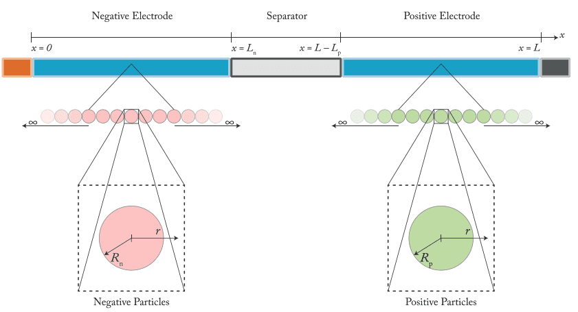
Physics-based battery models expose those internal variables. DFN, single-particle models, and their variants all report anode potential, local lithium concentration, and temperature fields as first-class outputs. Run a charging profile in simulation and you can track whether anode potential approaches unsafe thresholds, where thermal hotspots develop, and how much capacity loss accumulates over hundreds of simulated cycles. You're not just comparing charge times. You're comparing what happens inside the cell.
How model-based design fits the workflow
Model-based design for BMS charging validation follows a progression: parameterize a cell model, connect it to control logic, simulate under realistic scenarios, compare outcomes, refine. NREL's work on model-based design for large Li-ion battery packs frames the value as shortening time and cost for electric drive battery system design.
The general battery modeling workflow includes estimating cell model parameters, defining design specifications, and generating simulation-ready models for virtual verification. In this context, the BMS logic is the system under test and the battery model is the plant.
A caveat worth repeating: most model-based charging work in the literature is still at the R&D stage. Teams use simulation to understand what a chemistry and cell design can support, to identify which control rules matter most, and to quantify tradeoffs. Going from those insights to production BMS code involves embedded state estimation, real-time computational constraints, and hardware-in-the-loop validation that simulation alone doesn't address.
Inputs needed for a useful charging validation workflow
A charging validation workflow requires several categories of input.
Cell-level inputs include electrochemical parameters (exchange current density, diffusion coefficients, electrode thickness, particle size), thermal properties, and measured performance data such as rate capability and capacity versus cycle curves.
Pack-level inputs include cell count, series-parallel configuration, thermal management architecture, and cell-to-cell variation assumptions.
Operating assumptions define the scenarios you'll test: ambient temperature range, initial state of charge, charger power limits, and duty cycle profiles. The quality of these inputs directly determines whether simulation results are useful or misleading. Parameterization from measured data, rather than literature defaults, is where most of the upfront effort goes. Ionworks training resources cover practical approaches to this step.
Control logic that should be represented in the model
The simulation should represent the actual control logic the BMS will execute, or at least a reasonable abstraction of it: current ramp rates at the start of charging, voltage-based taper thresholds, temperature derating curves, SOC cutoff windows, and any cell balancing behavior during or after charging.
If you're comparing a rules-based strategy against a model-based one, both need enough fidelity for a fair comparison. A rules-based strategy with realistic taper and derating logic shouldn't be benchmarked against an idealized model-based controller with no computational or measurement latency.
Outputs that make strategy comparisons useful
Time to a target SOC (typically 80%) is the headline metric, but it means nothing without context.
Peak cell temperature, average temperature during charging, and thermal gradient across the pack tell you whether the strategy is thermally viable. Taper timing and current spread across cells reveal control behavior that affects both user experience and aging. Projected life impact, capacity fade per charge event or cumulative damage over a defined cycle count, connects the charging strategy to long-term product performance.
A practical workflow for validating charging strategy in simulation
The workflow below reflects how teams typically move from measured data to validated charging strategy. Each step builds on the previous one, and the cycle is designed to be repeated as new data or requirements emerge.
Step 1: Parameterize the battery model from measured data
Useful strategy validation starts with grounded parameters. Fitting a physics-based model to measured voltage, temperature, and capacity data ensures the simulation captures the cell's actual behavior under relevant conditions. Generic parameter sets from the literature may be directionally correct but are rarely accurate enough for quantitative strategy comparisons.
Step 2: Define objectives and operating constraints
Set clear targets: charge to 80% in under 20 minutes, minimize degradation per charge event, maximize energy throughput over the pack's warranty period, whatever matters for the product.
Pair targets with constraints: maximum cell temperature, minimum cell voltage during rest, acceptable lithium plating risk threshold, permissible cell-to-cell imbalance at end of charge. Defining these up front prevents the common failure mode of optimizing one metric while ignoring others.
Step 3: Simulate candidate charging profiles
Run competing strategies under identical assumptions. A typical comparison might include a baseline CC-CV profile, a two- or three-step constant-current profile, a temperature-derating variant of CC-CV, and a model-based profile that constrains current based on estimated anode potential.
Running all candidates against the same cell model, thermal assumptions, and operating conditions is what makes the comparison meaningful. Sequential bench tests rarely achieve that level of control.
Step 4: Test across realistic operating conditions
Vary temperature (cold, ambient, hot), initial SOC (10%, 30%, 50%), and use-case scenarios (daily commute charging, road-trip fast charge, fleet depot charging). A strategy that wins at 25°C and 10% initial SOC may fall apart at 0°C and 50%.
Scenario coverage is where simulation provides its biggest advantage over bench testing. The marginal cost of an additional simulated scenario is trivial. The marginal cost of an additional bench test is measured in cells, channels, and weeks.
Step 5: Compare tradeoffs and refine
Use the results to identify which strategies hold up across conditions and which are fragile. Refine taper thresholds, derating curves, or model-based constraints. Re-run to confirm the refinement improved target metrics without degrading others.
The refined strategy becomes the candidate for hardware-in-the-loop testing or bench validation. Simulation doesn't replace those steps. It makes sure you aren't wasting them on strategies that should have been eliminated earlier.
What simulation reveals that bench testing cannot
Physics-based simulation exposes internal electrochemical variables: anode potential trajectories, lithium concentration profiles at the electrode-electrolyte interface, and spatial temperature distributions within the cell. Lithium plating quantification during fast charging is an active research area precisely because direct measurement in operational cells is extremely difficult.
Simulation also enables far broader scenario coverage. You can test a strategy across hundreds of temperature and SOC combinations in a single batch, something that would require months of bench time and hundreds of cells.
Common mistakes in charging strategy validation
Overfitting to a single operating condition. A charging profile tuned for 25°C may cause excessive degradation at low temperatures or unnecessary conservatism at elevated temperatures. Test across the full range.
Ignoring thermal effects. A simulation that models electrochemistry without thermal coupling will underpredict temperature rise and miss the feedback loop between temperature, resistance, and degradation rate.
Using unvalidated model parameters. If the model doesn't match the cell's measured behavior, the strategy comparison is built on a faulty foundation.
Ignoring aging effects. A strategy validated for a fresh cell may not hold up after 500 or 1000 cycles as internal resistance increases and capacity fades.
How to evaluate BMS simulation software
When evaluating simulation tools for charging strategy validation, focus on four things.
Parameterization quality. Can the software fit physics-based model parameters from your measured data, or does it rely on generic libraries? Direct parameterization from cell characterization data produces more reliable comparisons than literature values.
Control logic integration. Can you implement realistic BMS logic (taper rules, derating curves, balancing behavior) alongside the battery model? You need the control strategy and the plant in the same simulation.
Scenario testing efficiency. Can you sweep across temperatures, initial SOC, and duty cycles in batch runs? If each scenario requires manual setup, the workflow collapses back toward the sequential testing bottleneck simulation is supposed to eliminate.
Iteration speed. Can you run enough simulations to meaningfully compare strategies within a development sprint?
The software should also surface internal-state outputs: anode potential, concentration profiles, temperature distributions, degradation indicators. Without those, you're running a charge-time calculator.
BMS simulation software evaluation matrix
Evaluation criterion
What to look for
Red flags
Parameterization
Fits electrochemical model parameters directly from your measured cell data
Relies solely on generic material libraries or requires manual parameter entry from literature
Control integration
Supports custom BMS logic (taper, derating, balancing) connected to the battery model
Battery model and control logic are separate tools with no co-simulation capability
Scenario coverage
Batch sweeps across temperature, SOC, and duty cycle with automated result comparison
Each scenario requires manual setup; no built-in sweep or batch capability
Iteration speed
Runs hundreds of charging profiles in hours, not days
Single simulation takes longer than the equivalent bench test
Internal-state outputs
Reports anode potential, concentration gradients, temperature distribution, degradation metrics
Only outputs terminal voltage and surface temperature
Model fidelity options
Supports equivalent circuit, single-particle, and full electrochemical (P2D) models
Locked to a single model type with no option to trade fidelity for speed
Ionworks is built around this workflow: parameterization from measured data, physics-based electrochemical models, and batch scenario testing designed for charging strategy comparison.
Where this fits in the broader battery development loop
Charging strategy validation is one piece of a broader development loop that Ionworks frames as measure, train, predict, optimize. You measure the cell's behavior through characterization testing. You train a physics-based model by fitting parameters to that data. You predict how the cell will respond to candidate strategies under various conditions. You optimize by iterating through simulation before committing to hardware.
Ionworks is built on PyBaMM, the open-source battery modeling framework. The design reflects a practical observation: pure AI doesn't work for battery problems. The physics are too context-dependent and the parameters evolve too much over the cell's life for a purely data-driven approach to generalize well. Physics-based models provide structural understanding; machine learning accelerates parameterization, prediction, and optimization. You need both.
Charging strategy validation sits in the predict-and-optimize phases. The quality of predictions depends entirely on the measurement and training steps that precede them. Teams that invest in good characterization data and careful parameterization get results they can act on. Teams that skip those steps get results that look plausible but don't hold up against real cells.
Frequently asked questions about BMS simulation for charging strategy
What is battery management system simulation? It uses physics-based electrochemical models to predict how a cell or pack will respond to specific control logic and operating conditions. Instead of building hardware and running physical tests, teams run virtual experiments. Those experiments expose internal states that bench testing can't measure directly: anode potential, temperature gradients, lithium concentration profiles.
Why is simulation used for charging strategy validation? Comparing strategies on the bench requires weeks per strategy per condition. Simulation evaluates hundreds of combinations in hours and provides visibility into internal degradation mechanisms like lithium plating that are invisible to external sensors.
What's the difference between rules-based and model-based charging control? Rules-based control uses fixed thresholds and lookup tables. Taper at a set voltage. Derate above a temperature limit. Model-based control estimates internal cell states (anode potential, local lithium concentration) in real time and adjusts current accordingly. Rules-based is production-ready and field-proven. Model-based extracts more performance, but it needs validated parameters and embedded compute resources that most production BMS platforms don't yet support.
What should teams evaluate when choosing BMS simulation software? Four things: (1) whether it can parameterize physics-based models from your own measured cell data, (2) whether it supports co-simulation of battery models and BMS control logic, (3) whether it can run batch scenario sweeps efficiently, and (4) whether it outputs internal electrochemical states alongside terminal voltage and charge time.
Can simulation replace bench testing? No. Simulation compresses design space exploration and helps teams arrive at bench testing with a well-informed strategy. Hardware-in-the-loop testing and physical cell validation are still necessary before production. The goal is fewer bench iterations, not zero.
Conclusion
Better charging strategy comes from better-modeled tradeoffs. BMS simulation gives battery and BMS teams a way to compare candidates under controlled, repeatable conditions, with visibility into internal electrochemical states that bench testing can't observe.
Most model-based charging work is still at the R&D stage. Production deployment requires embedded BMS hardware, validated state estimators, and control logic that runs within real-time budgets. Simulation doesn't change that. What it does is make sure that when you reach hardware validation, you're testing strategies that have been vetted against the physics, not strategies inherited from the last program or tuned to a single bench condition.
The charging strategy your product ships with shapes customer experience, warranty exposure, and long-term brand perception. Validating it through simulation, grounded in measured data and physics-based models, is how battery teams move from educated guesses to engineered decisions.
Frequently asked questions
Continue reading