Most battery digital twin projects stall for the same reason: the team never agreed on what the twin is supposed to decide. A cell R&D group wants to understand lithium plating risk during fast charge. A controls team wants a model that runs in real time on embedded hardware. A systems engineer wants to evaluate thermal management strategies across a 96-cell pack. All three call their work a "digital twin," and all three need fundamentally different models.
The confusion is expensive. When scope stays vague, teams either build a model too detailed to run at system scale or too coarse to capture the electrochemistry that sets real operating limits. Wrong cell assumptions propagate into pack sizing, thermal margins, and control tuning, leading to overbuilt systems that cost too much or underbuilt systems that fail too early.
This guide maps four levels of battery digital twins to the engineering decisions they serve, compares cell-level and system-level approaches directly, and offers practical guidance on choosing the right fidelity.
In short
Cell-level digital twins are the right tool for R&D decisions: parameterization, degradation studies, fast-charge limit setting, and design tradeoffs. System-level digital twins (module, pack, BMS) serve controls development, thermal management, pack sizing, and operational monitoring.
Module and pack twins typically require reduced-order representations of cell behavior to remain computationally tractable. BMS twins need fast, executable models that fit deployment constraints. The strongest workflows connect both levels, starting with validated cell physics and reducing fidelity deliberately as models move toward system integration.
What a battery digital twin means in practice
A battery digital twin is a model, plus measured data, plus engineering context, tied to a specific decision loop. The model alone is not a twin. The data alone is not a twin. The combination, when updated against measurements and used for prediction, is what earns the label.
The scope of the twin determines what fidelity is useful. A twin built for parameterizing electrode kinetics needs to resolve solid-phase diffusion. A twin built for SoC estimation on an embedded BMS does not.
Calling everything a "digital twin" without specifying the asset, the decision, and the update mechanism leads to projects where the model never connects to the engineering problem it was meant to solve.
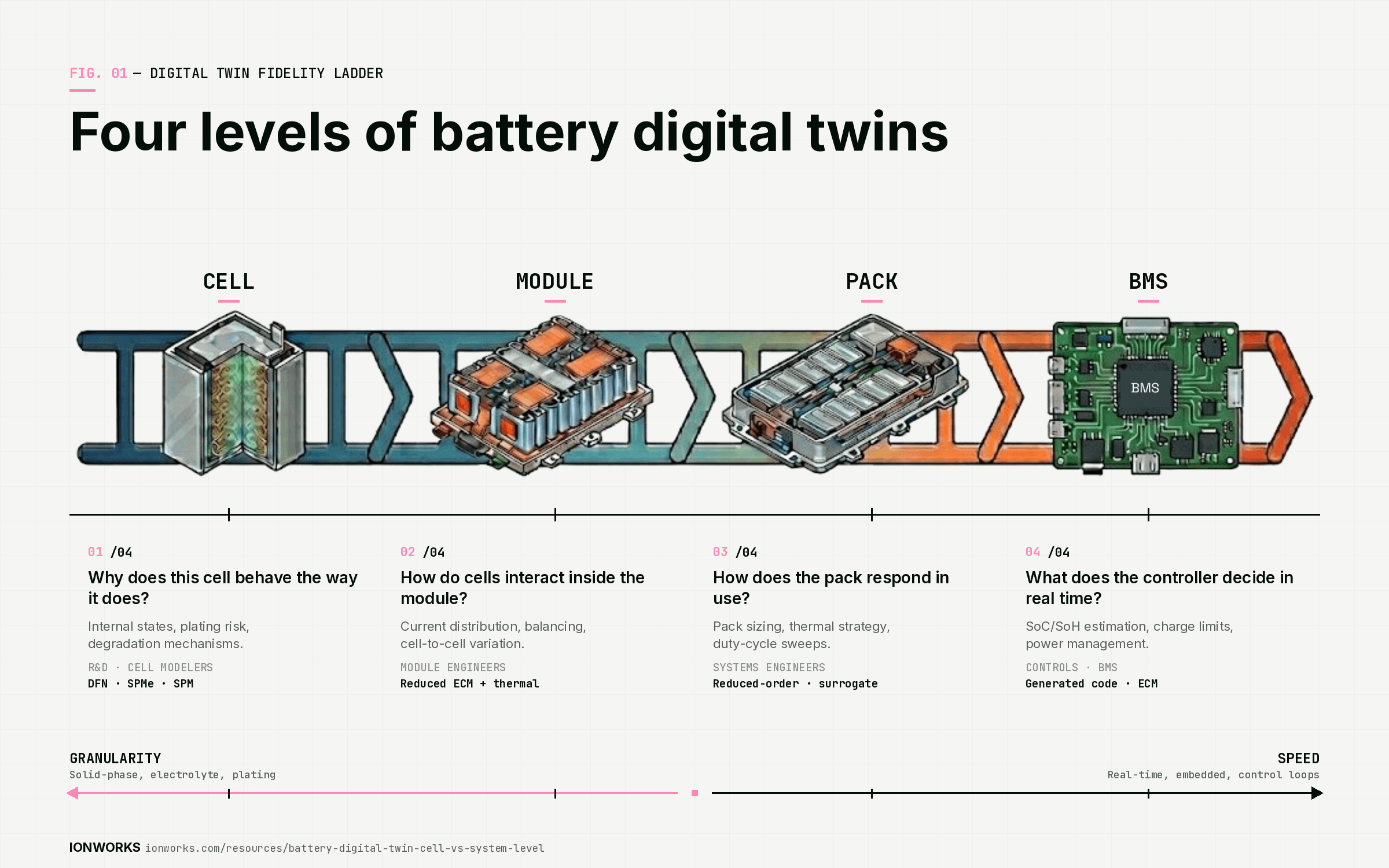
The four levels of battery digital twins
Cell-level digital twin
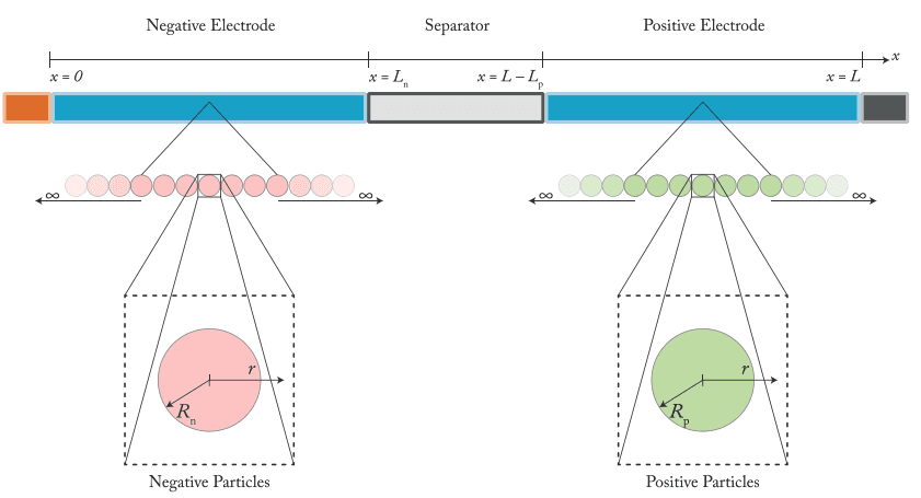
Cell-level twins focus on electrochemical behavior inside a single cell. They are the right tool for parameterization and validation, fast-charge limit studies where lithium plating risk matters, degradation mechanism analysis, and cell design tradeoffs like electrode thickness or porosity.
Physics-based electrochemical models (SPM, SPMe, DFN) operate at this level. The data requirements are correspondingly richer: half-cell measurements, teardown data, rate capability sweeps, and HPPC profiles feed these models. The payoff is direct access to internal states that no sensor can measure in a fielded pack.
Module-level digital twin
Module-level twins focus on how cells interact. They capture current distribution effects caused by cell-to-cell variation, thermal coupling between adjacent cells, and balancing behavior across series-parallel configurations.
Capacity and resistance differences between cells amplify at the module level and can accelerate aging and degradation. Module design often lacks direct access to individual cell currents and temperatures, so modeling is needed to infer cell-level behavior inside the module.
Pack-level digital twin
Pack-level twins add the enclosure, cooling system, and integration constraints. They are the right level for thermal management strategy evaluation, pack sizing and architecture tradeoffs, and duty-cycle studies that span hundreds or thousands of operating scenarios.
Running a full electrochemical model for every cell in a pack is rarely practical. Pack twins typically rely on reduced-order cell representations scaled across the system.
BMS-level digital twin
BMS-level twins focus on estimation and control. SoC and SoH estimation, diagnostic logic, charge and discharge limits, and power management all need models that execute in real time on constrained hardware. For a deeper look at the BMS side, see our guide to battery management system simulation for charging strategy validation.
High-fidelity battery models are useful for system design validation and simulation-based training, but are often too expensive or too slow for control design, state estimation, and embedded real-time use. A low-order, code-generation-friendly surrogate is more practical for these applications.
Cell-level vs system-level models
The distinction is not about which model is "better." It is about which question you are trying to answer.
| Dimension | Cell-level model | System-level model |
|---|---|---|
| Primary question | Why does the cell behave this way? | How does the system behave in use? |
| Typical fidelity | Electrochemical, physics-based | Reduced-order, control-oriented |
| Primary teams | R&D engineers, cell modelers | Systems engineers, controls and BMS teams |
| Runtime target | Minutes to hours per simulation | Milliseconds to seconds per step |
| Data needs | Rich test data, teardown, half-cell | Aggregated behavior, calibration data |
| Best outputs | Internal states, mechanisms, limits | Voltage, temperature, control response |
Cell models explain mechanisms. System models support execution. Programs that skip the cell-level work tend to discover the consequences during system integration, when fixes are most expensive.
The quality of the handoff between these levels determines how much value the downstream model retains. A system model built on poorly parameterized cell assumptions inherits every error in those assumptions.
Where electrochemical models fit
Electrochemical models are the natural choice for cell-level R&D questions. They capture internal states directly: solid-phase concentration gradients, electrolyte potential distributions, lithium plating onset conditions, and SEI growth mechanisms. Equivalent circuit models do not resolve these mechanisms.
PyBaMM spans multiple fidelity levels within the electrochemical modeling space, including SPM, SPMe, and DFN formulations, along with half-cell models, thermal coupling, and parameterization workflows. It also supports direct comparison of full and reduced-order electrochemical models, which is valuable when deciding how much fidelity to preserve as models move downstream.
The tradeoff is data. Physics-based electrochemical models require stronger parameter evidence than ECMs. A full DFN model needs electrode-level properties: particle radii, diffusion coefficients, exchange current densities, and transport parameters. Teams that lack teardown or half-cell data may need to start with lumped physics-based approaches — fitting dimensionless groups like the diffusion timescale τ = R²/D directly, instead of trying to recover quantities the full-cell experiment cannot resolve — and move toward full electrochemical models as the evidence base grows.
Where reduced-order models fit
Reduced-order models serve controls, deployment, and system-scale studies where runtime budget is tight and the question is "what happens" rather than "why it happens."
Common examples include equivalent circuit models (ECMs) for SoC and SoH estimation, reduced electrochemical surrogates for pack simulation, state-space models for control design, and pack-level ROMs for thermal management. MathWorks describes a battery modeling workflow where teams estimate cell parameters, define battery design, choose model resolution, and generate Simulink libraries for design verification, BMS development, sensitivity studies, and thermal management.
Reduced-order models are not shortcuts. They are purpose-matched to different runtime and deployment constraints. A well-constructed reduced model derived from validated electrochemical physics retains the behavior that matters for system decisions while shedding the computational overhead that the system workflow cannot afford.
Simplified electrochemical models after model order reduction and linearization can serve real-time control applications where traditional P2D and SPMe formulations are too expensive to run directly.
How to choose the right fidelity
| Decision | Recommended model class | Why |
|---|---|---|
| Parameter estimation | Electrochemical or lumped physics-based | Mechanism-level fit required |
| Fast charging limits | Electrochemical or reduced electrochemical | Plating and thermal insight needed |
| Pack sizing | Reduced-order from validated cell model | Scalable system studies across configurations |
| Thermal strategy | Pack or module reduced-order | Runtime across many scenarios |
| BMS algorithm testing | ECM or control-oriented surrogate | Executable speed on target hardware |
| Embedded deployment | Generated code model | Runtime and portability on constrained platforms |
Start from the engineering question, not the model catalog. Match fidelity to the risk associated with the decision, to the data you actually have, and to the runtime budget the workflow imposes.
Avoid maximum fidelity by default. A DFN model running every cell in a 96-cell pack is technically possible but rarely the right use of compute time when the question is about pack-level thermal distribution.
Why accurate cell models matter upstream
Cell-level assumptions propagate through every downstream model. Wrong open-circuit voltage curves distort SoC estimation. Wrong resistance values distort thermal margin calculations. Wrong degradation dynamics distort operating window definitions. Wrong rate capability assumptions distort fast-charge protocols.
The consequences compound in both directions. Overbuilding (adding extra cells, oversizing cooling systems, applying overly conservative limits) raises cost and mass without proportional benefit. Underbuilding (using aggressive limits, undersizing thermal management) raises warranty risk and shortens field life.
A validated cell model that accurately captures rate-dependent behavior, thermal sensitivity, and aging trajectory gives pack designers and controls engineers a foundation they can trust. Without that foundation, every downstream model carries inherited uncertainty that no amount of system-level calibration can fully correct.
The Ionworks angle
Best for: Deep cell-level battery modeling grounded in electrochemical physics, with reproducible parameterization workflows built around PyBaMM.
Strengths:
- Cell-level modeling depth. Ionworks focuses on the electrochemical layer where operating limits, degradation mechanisms, and design tradeoffs are set. Cell models built in Ionworks connect measurements directly to simulations through parameterization and validation workflows.
- PyBaMM-native workflows. Modeling in Ionworks uses PyBaMM's ecosystem of SPM, SPMe, DFN, and thermal formulations. Teams working with PyBaMM battery modeling workflows can parameterize, compare model fidelities, and validate against held-out test data within a single environment.
- Reproducible parameterization studies. Models stay tied to the measurement data and fitting choices that produced them. When a cell design changes or new test data arrives, re-parameterization follows a traceable path rather than starting from scratch.
- Handoff to system simulation. Ionworks generates Simulink, MATLAB, or C++ code from validated cell models. The cell model remains the source of truth; reduced outputs and generated code feed broader pack, module, and BMS simulation environments.
- Traceable model handoffs. The connection between a validated cell-level electrochemical model and the reduced-order artifact deployed in a Simulink battery model or C++ integration stays documented. When system-level results look wrong, teams can trace back to the cell-level assumptions that produced them.
Limitations:
- Cell-level scope by design. Ionworks does not aim to be a full pack or BMS simulation platform. Teams needing module-level thermal-electrical co-simulation or BMS algorithm testing will use Ionworks outputs inside other tools, not replace those tools.
- Requires quality cell data. Physics-based electrochemical models demand richer input data than ECMs. Teams without half-cell data, rate capability sweeps, or HPPC profiles may need to build their measurement program before getting full value from the modeling workflow.
The best starting point for avoiding downstream sizing and control mistakes is a validated cell model. The best endpoint is deployable system behavior. The handoff between the two should stay traceable and reproducible so that when something goes wrong at the pack or BMS level, teams can identify whether the root cause is in cell assumptions or system integration.
Recommended workflow
A practical sequence that connects cell-level depth to system-level deployment:
- Measure cell behavior carefully. Rate tests, HPPC, cycling aging, and (when possible) half-cell and teardown characterization.
- Parameterize the cell model. Fit electrochemical parameters against measured data using SPM, SPMe, or DFN formulations as warranted by data quality and the engineering question.
- Validate against held-out tests. Confirm predictive accuracy on conditions not used during fitting. If validation fails, revisit parameter choices or model structure before moving downstream.
- Reduce for system use cases. Generate reduced-order representations, equivalent circuit fits from electrochemical behavior, or code artifacts (Simulink, MATLAB, C++) suitable for pack simulation and BMS integration.
- Deploy into pack and BMS tools. Use the reduced cell model inside module, pack, or BMS simulation environments for thermal studies, sizing, controls development, and hardware-in-the-loop testing.
Use richer models upstream. Use faster models downstream. Keep provenance across handoffs so that when a cell design revision arrives or a new use case emerges, the re-parameterization and revalidation path is clear.
Final verdict
| If the goal is... | Best starting point |
|---|---|
| Understand cell behavior | Cell-level electrochemical model |
| Build pack tradeoff studies | Reduced-order system model |
| Test BMS algorithms | Control-oriented executable model |
| Avoid sizing mistakes | Validated cell model first |
| Connect R&D to deployment | Cell model plus generated code |
Cell-level and system-level battery digital twins solve different problems. The right choice depends on the decision type, the available data, and the runtime budget.
The teams that get this right preserve traceability from electrochemical parameters through generated Simulink, MATLAB, or C++ code to the system simulation where the final design decision happens. That traceability is what separates a useful digital twin program from a collection of disconnected models.
Next steps for your team: Evaluate your current model handoffs between cell-level and system-level work. Identify where fidelity drops earlier than the decision requires, or where runtime constraints block adoption of models that have already been validated. Build from validated cell models and extend into system simulation with full awareness of what was kept, what was reduced, and why. See how Ionworks supports this workflow or explore the underlying parameterization approach.
Continue reading